These instructions show the steps to be completed to create initial LibreRouter Device connections. Read this important information prior to powering on the device.
What is required?

- A LibreRouter kit
- PoE injector
- PoE splitter
- SFTP Exterior Network Cable (with 4 pairs of braided filaments, double plastic sheath, metal mesh covering and additional filament for grounding).
- Shared RJ45 network sheets.
- Shielded RJ45 network sheets.
- Bipolar electric cable. Spear.
This is a list of the materials, supplies and devices you may need. The LibreRouter Kit is included with the device as well as the antennae with their holders and four coaxial cables, as outlined in What is a LibreRouter.
The rest of the required elements and supplies must be purchased based on the needs of each installation and the Community Network planning.
The various connection options for adapting them to the needs of each Community Network are explained below. Let’s go! Reading all of this material will help you make good decisions.
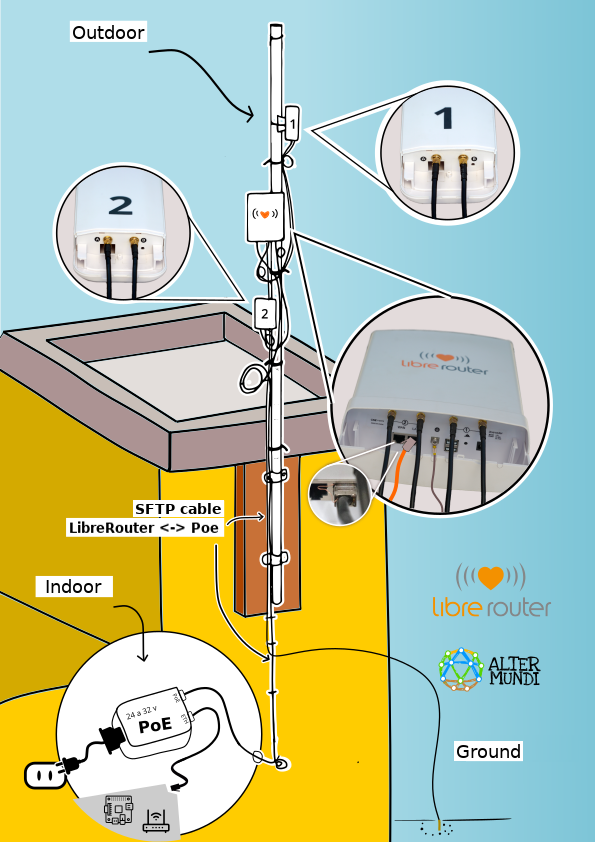
Example of complete LibreRouter Node and connections
The image below is a visual summary. It shows the connections that are necessary as an example of assembling a LibreRouter node on a wall using energy with a PoE injector. Use this quick guide.
Let’s get started!
1) Connect the antennae
This is a LibreRouter Device with connected antennae
It should end up like this once the steps outlined below have been completed.

Place the antennae holders.

Connect the coaxial cables to the antennae.
- Hold Antenna 1 and open the protective cover.
- Thread the cables through the holes in the protective cover.
- Connect the coaxial cables at connectors A and B.
- Adjust the dial until it stops.
- Replace the protective cover.
- Complete the same process for Antenna 2.

2) Connect the LibreRouter Device antennae.
- Hold the Antenna 1 Connector A cable.
- Twist Connector A on the LibreRouter Device following the connectors marked with the number 1.
- Complete the same procedure with the Connector B cable.
- Complete the same process for Antenna 2.

When you have finished, ensure that connectors A and B on each Antenna are in order and connected to the corresponding Antenna following the number (1 and 2).
📌 Remember
The connectors should be aligned in order to twist them. One frequent issue develops when the dials are forced when they are not aligned. To avoid this, place the coaxial cable connector across from the device or antenna connector. Press down lightly so that the dials make contact and then turn the cable connector screw with your hand until it is completely fastened.
The copper tip of the connector may not enter the orifice and may push the metallic contact of the other connector inside. The original position can be restored by pushing it lightly using a pointed object.
Make the final adjustment of all of the connectors with a half-turn using an 8 mm wrench or tweezers when you assemble it in its final location.
If the cable connectors and box twist together, stop and repair. In some cases, failing to affix the connector to the plastic box and cable that is inside of the box makes it turn with the connector and it may be damaged. To address this situation, open the box and carefully unscrew the connectors. Next, loosen the screw that holds the connector to the box using an 8 mm wrench or tweezers. Turn the screw until it is halfway in. Place a small amount of epoxy (Poxipol) inside, covering the contact between the internal cover of the connector and the box. Turn the screw until it is tight before the epoxy dries, and then wait for the glue to dry.
3) Connect the LibreRouter Device power source.
It is important to determine how the device will connect to an energy source. There are various options that should be assessed based on the needs of each node and Community Network.
The LibreRouter Device can be plugged into the electrical socket (110V-220V) or connected to a solar panel or alternative energy source batteries.
Connected to a power source (110 or 220 V)
- OPTION 1: Using a PoE Injector
- Use an SFTP Network Cable of a length that allows the LibreRouter Device to be connected to the outside of the dwelling using an outlet inside the building.
- Connect one end of the cable to the LibreRouter Device LAN Port.
- Connect the other end to the Injector PoE Port.

- OPTION 2: With a PoE splitter.
- Use an SFTP Network Cable of a length that allows the LibreRouter Device to be connected to the outside of the dwelling using an outlet inside the building.
- Connect one end of the cable to the LibreRouter Device LAN Port.
- Connect the other end to the PoE Splitter.
- Connect a transformer in the cylindrical connector of the PoE Splitter and plug it into the socket inside the dwelling.

📌 IMPORTANT: Read all of this material. Details for assembling this cable with grounding that should be incorporated into this type of connection are provided below.
Powered directly by a battery
The LibreRouter Device may be connected to a 12V battery. There is also a 12V to 36V battery system. There are two simple options for completing this:
- OPTION 1: With a bipolar copper cable:
- Obtain a copper cable with two conductors that are each at least 1 mm in diameter (also known as a polarized workshop-type cables). If both conductors are the same, you will need to use a multimeter to mark the polarity of the two ends.
- Place a cylindrical charge connector (5.5 mm x 2.1 mm) to one end.
- Connect the battery clamps to the other. Note: The central pin of the connector goes to the positive on the battery. Connecting it incorrectly may damage the LibreRouter!

- OPTION 2: With a network cable: A PoE Injection is completed directly using this option. It is only valid when the battery is very close to the Device. It allows the connection to be made using a copper network cable measuring up to 20 meters.
- Assemble the upper end of the cable with a sheathed RJ45 card.
- Connect this end to the LAN connector on the LibreRouter Device.
- Connect the brown cables to the negative clamp (-) on the battery.
- Then connect the Blue pair to the positive clamp (+).
- The green and orange pairs can be used to connect the other devices to the LibreRouter, assembling a simple RJ45 card using the same sequence of colors used on the other side, but leaving the brown and blue pairs that were used with the battery empty.

📌 Keep in mind:
A second LibreRouter Device can be connected in the WAN. This allows the energy source and data cabling connection to be shared. The source must be measured again so that it can reach both Devices. It should never receive over 36V.
If the Device constantly restarts, it may not be receiving enough energy. In these cases, consider using a source that sends more current (amps) or a source with more tension (volts). We did some testing, and this material may be helpful.
4) Install the device’s electricity protection
It is important to install a good grounder on the LibreRouter device. This has a grounding contact that is the terminal subject with a screw located in the center of the Device.
The next two steps outline the recommended procedure with an example using PoE Injector energy. The same steps consider protecting the device against electrical storms and static accumulation while protecting the residents of the dwelling or building.

- STEP 1: Connect the grounding terminal on the LibreRouter Device.
- Look for a cable that is long enough to go from the Device location to the ground. It can be a copper or network cable.
- Place end in the the LibreRouter Device grounding terminal, ensuring that it has firm and very solid contact.
- Bury the other end in the ground as close to the device as possible. Optional: You may place a javelin to improve contact.
- STEP 2: Connect the SFTP network cable to the PoE injector.
- Use the SFTP network cable. This has an isolation mesh and filament that reduces the tension generated by nearby electric shocks and helps to guide the static that the cable accumulates.
- Assemble the network cable that connects the LibreRouter Device to the PoE Injector.
- Place a sheathed RJ45 network card on one end of the cable. View the how-to video.
- Attach the other end of the cable using a shared RJ45 card. Follow these instructions.
- Connect the end with the Covered RJ45 card to the LibreRouter Device LAN port.
- Connect the end with the shared card to the LAN port of the PoE Injector.
Great! Our LibreRouter Device is protected from electric shocks 🙂
📌 Please note
Do NOT ground with the dwelling or building grounding connection. This will prevent an electric shock on the exterior from entering through this route.
5) Plug in and test
The LibreRouter device is ready with all of its cables connected! When you connect to the energy source, the LibreRouter Device will automatically power on. One way to confirm this is to check the LED lights on the back of the case.
Once the device has been on for two minutes, you may proceed with the initial configuration. These instructions can be used for this procedure.
📌 Possible uses of LAN and WAN Ports.
- LAN Port/ PoE Source
LAN means local area network. This port can be used to connect:- Devices that are part of the local network.
- To a device that has services and/or contents for the local network.
- Connect an internal router to improve connectivity within the home or entity in which the node is located.
- A switch or router expands the option for cabled connections to nearby locations.
- WAN Port
- This can be the nexus between the Community Network and other networks.
- It is normal to use it to connect the Community Network to the Internet. The Internet service provider company or entity device is connected in this port. This device is normally configured such that merely having a WAN connection allows the devices to communicate and the community network can use this link automatically (DHCP configuration). If this is not the case, coordinate with the entity or company to ask them to activate the DHCP or to obtain the information and configure the LibreRouter in accordance with the information provided.
- This connector also works as a PoE energy outlet that can be used to power a second device (PoE-Passthrough functionality). For more information, see foro.librerouter.org.

